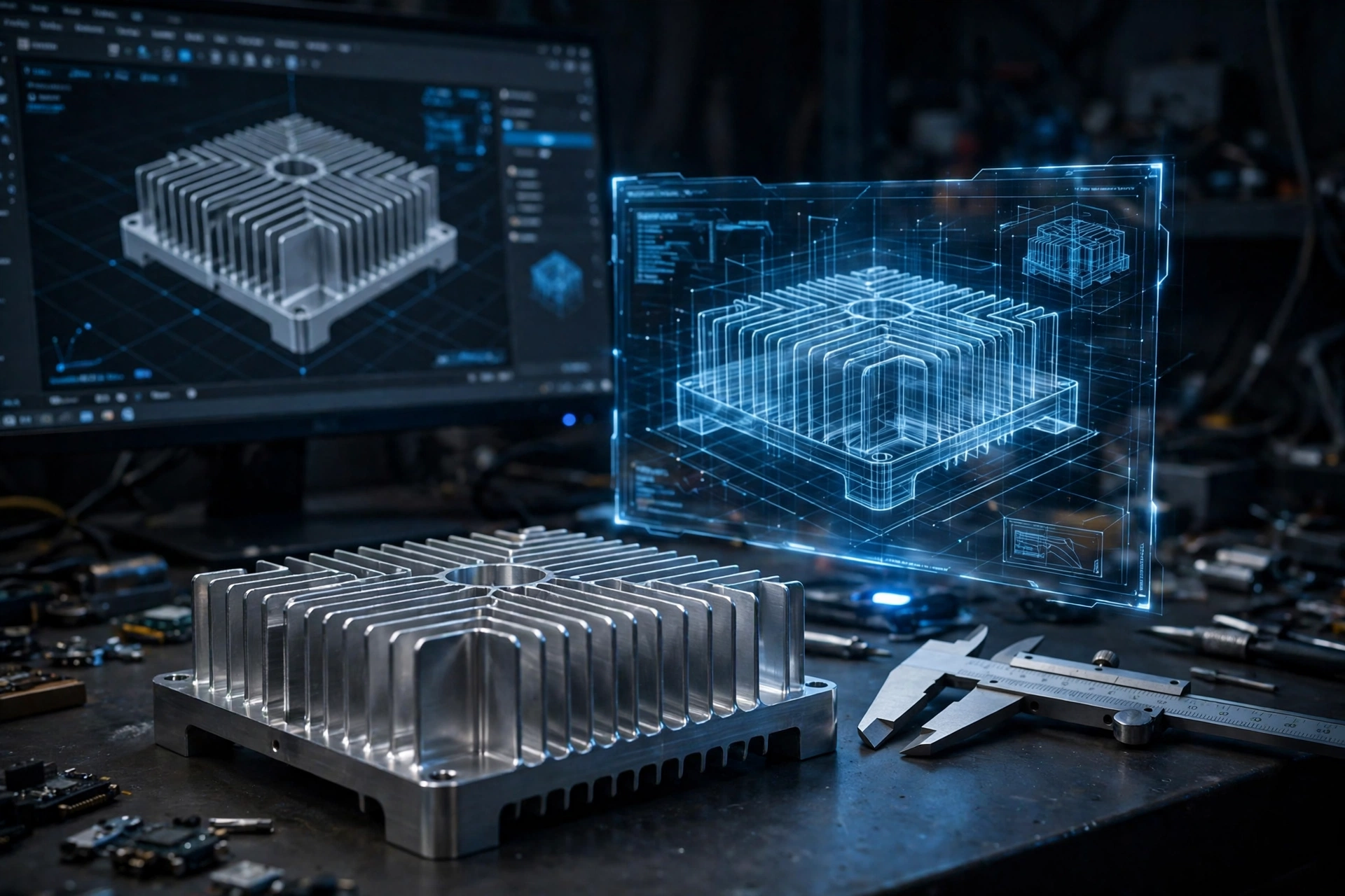
An aluminum heat sink can look finished long before it is ready for production. Its fins are evenly patterned, the mounting holes line up, and the CAD assembly shows a comfortable fit inside the enclosure. Then the design reaches a thermal engineer or manufacturing supplier, and a new set of questions appears: Which way does air actually travel? Can the proposed fin geometry be manufactured? Where will the part be held during machining? What does the drawing require the supplier to inspect?
This is not a failure of CAD. A solid model is excellent at describing geometry; it does not automatically resolve airflow, process limits, tooling access, or production inspection. For product designers developing an air-cooled heat sink, six early checks can prevent a clean-looking model from becoming an expensive late-stage redesign.
1. Model the Air Path, Not Just the Heat Sink
A heat sink rarely operates in the empty space shown in a standalone CAD render. The final assembly may include a fan, cable bundles, circuit boards, filters, covers, and openings that redirect air or let it bypass the fins.
Before fixing the fin geometry, identify whether the design uses natural convection or forced airflow. For passive cooling, orientation and clear vertical passages can be decisive. For fan-assisted cooling, the available pressure matters alongside the advertised airflow rating; a fan’s free-air CFM value does not describe what it will deliver through a restrictive enclosure.
An assembly-level CAD review should reserve realistic inlet and outlet space, show the direction of flow along the fin channels, and identify nearby obstructions. The flow length through the fins is also important: changing the cut length of an extrusion can change both the heated airflow path and pressure loss.
2. Check Fin Spacing Before You Add Another Pattern Instance
Adding more fins is an easy CAD operation. Improving cooling by adding fins is a different question.
Consider two simplified plate-fin layouts that each occupy a 100 mm width and use 1.5 mm-thick fins. If the outer fins sit at the edges and every gap is equal, 15 fins leave about 5.5 mm between adjacent fins; 25 fins reduce that gap to about 2.6 mm. The second arrangement has more nominal fin area, but also much narrower air passages.
These numbers are a geometric illustration, not a thermal performance comparison. The better choice depends on the flow available, fin height, fin length, orientation, and the fan or natural-convection conditions. With a fixed fan, reducing the gap may raise system resistance enough to lower the delivered airflow.
It helps to distinguish fin pitch from the open gap. Pitch includes fin thickness; the gap does not. That difference belongs on the drawing, not just in the pattern feature inside the model. A practical discussion of heat sink fin spacing shows why there is no single optimum gap that can be copied between passive and forced-air products.
Figure 1. Equal-width conceptual fin arrays. Gap values describe geometry only, not measured cooling performance.
3. Choose a Manufacturing Route That Matches the Geometry
An attractive cross-section is not automatically a practical extrusion. Extruded aluminum heat sinks are often economical for repeat production, especially when an existing profile or die can be used, but feasibility depends on the complete shape: fin height, thickness, spacing, base thickness, overall width, alloy, and die design.
If a design needs tall, very thin, closely packed fins, skiving may offer a different route. It forms fins from the parent metal, making dense one-piece structures possible in aluminum or copper. Larger assemblies or unusually tall fins may instead justify a bonded-fin construction, in which fins are joined to a base.
None of these processes is universally superior. The best choice depends on the thermal requirement and production quantities as much as on the shape. Before detailing every slot and fillet, ask a supplier to review a simple section view and the expected order volume. A small early geometry change may avoid a more expensive process later.
4. Give the Mounting Face Its Own Requirements
A heat sink is not only a fin array. The surface contacting the heat-generating component has its own engineering job, and it may be more sensitive to manufacturing variation than the outer envelope.
Flatness, surface finish, thermal interface material, and clamping method all affect the heat transfer path. Large bases and asymmetric machining can also respond to residual stress or fixture release. For that reason, specifying a perfectly flat-looking CAD plane is not enough: the engineering drawing should identify the functional contact region, the required datum scheme, and any flatness or roughness requirement that follows from the component supplier’s mounting guidance.
Avoid automatically applying the same tight tolerance to every surface. Precision is valuable where it supports contact or assembly; elsewhere it may only increase inspection time and cost.
5. Leave Room for Secondary Machining and Assembly
Mounting holes, tapped features, cable clearances, and alignment bosses often enter the model after the thermal shape is established. Their position can create manufacturing problems if a drill must approach through a dense fin field, a cutter cannot reach a pocket, or a fastener has no installation clearance.
For an extruded profile, the production sequence may include cutting to length, CNC machining, deburring, surface finishing, and assembly. Designers should consider which features can be created in each operation and which surfaces can serve as reliable locating or clamping datums.
A quick interference check should go beyond the part itself. Include the tool approach where relevant, screw-head and driver access, the thermal interface area, cable routing, and the space needed to install or replace the finished heat sink. If anodizing or another finish is specified, identify critical contact or threaded areas that may need special treatment or masking.
6. Make the CAD Handoff a Manufacturing Specification
A STEP file communicates nominal geometry, but it does not tell the supplier which dimensions control product function, which surfaces need inspection, or whether a shape is merely a concept awaiting thermal validation.
A useful release package combines a neutral 3D model with a controlled drawing and a short requirements summary. At minimum, it should state the heat source and allowable temperature, available envelope, airflow conditions, material preference, critical contact surfaces, hole and thread details, finish requirements, production quantity, and inspection expectations.
The distinction between a prototype and repeat production should be explicit. A geometry that is reasonable for five CNC-machined prototypes may not be economical for several thousand parts; conversely, a custom extrusion die may be difficult to justify for a one-off build.
One practical habit is to mark the drawing with two kinds of constraints: features that cannot change because they control thermal or mechanical function, and features that the manufacturer may adjust after review. That gives the supplier room to improve manufacturability without silently changing design intent.
The CAD-to-Production Checkpoint
Before releasing a heat sink for quotation or tooling, ask the team to answer six questions: Is the real air path represented? Is the fin gap appropriate for that airflow? Is the cross-section suited to a realistic manufacturing process? Are the mounting-face requirements defined? Can secondary operations and assembly be performed? And does the drawing explain what must be inspected?
None of these checks replaces detailed thermal analysis or testing. They make that work more useful by aligning the model, the production method, and the actual installation. The goal is not simply a heat sink that looks right on screen, but a component that can be built consistently and perform as intended in the product.
About the Contributor
This article was contributed by XINXIANG, a manufacturer of aluminum and copper heat sinks using extrusion, skiving, bonded-fin construction, and secondary machining.