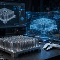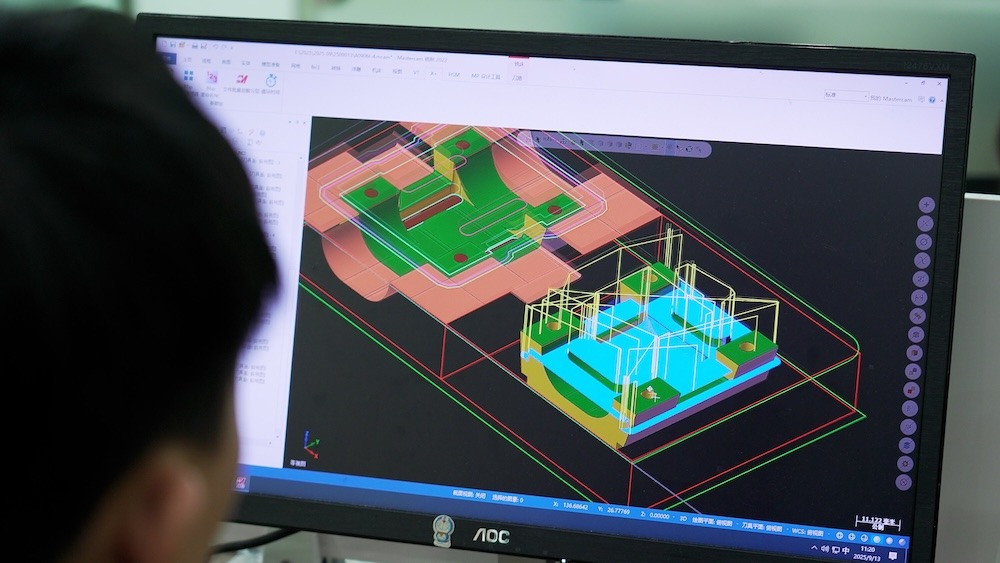
A detailed CAD model can be used to define the desired geometry of a component. However, when the model is complex with features like deep pockets, thin walls, undercuts, internal radii and complex faces, a few considerations for manufacturing will need to be made. Turning your design into reliable custom machined parts will involve some engineering considerations for how the tool can reach the part, how it will be held, how it will be machined, tolerances and how it will be inspected. The objective is not to only reproduce the model but to ensure you can manufacture the part consistently.
A Complete CAD Model Is Not Yet a Manufacturing Process
Whilst a CAD model will have all the information you need on dimensions, geometry and intent; more information will be required to manufacture. The model may have all the surfaces and features required to assemble the part but you may not know which surfaces to machine first, how to locate the workpiece and what features need to be referenced against a common datum. The engineer will need to interpret and understand the design to create a manufacturing process that can be carried out using the available machines and cutters.
When there are multiple features within a component you may need a long tool to machine the deep cavity. However, if there is a narrow slot close by, you may not be able to use a large diameter tool. Internal corners with a very small radius may not be possible to machine using standard milling cutters without extra processes. Undercuts may also be present in the model but not easily accessible when machining using a standard 3-axis set up. These factors can affect what tools you can use, how long it will take to machine, surface finish and accuracy.
The model will also need to show functional requirements. There may be many dimensions on the component but only a few will control how it will assemble, seal, move and transfer load. It is important to identify what these are and how they relate to each other. For example, a bore, mounting face and bolt pattern may all need to be referenced against a common datum. Without understanding this, individual features may be within tolerance but the whole component may not assemble correctly.
WayKen will carry out an engineering review to help with this. When using our precision machining service, we will carry out a design for manufacturing review. Our engineers will look at the geometry, tolerances, material and any potential issues. This will help us to understand if the design can be machined as it is or if any changes need to be made before custom machined parts enter production.
DFM Identifies Geometry That Creates Machining Risk
Design for manufacturability considers what aspects of your design might cause issues with manufacturing, and how you can ensure good quality, and reasonable cost. In terms of CNC machining, this would include considering if cutting tools can reach the correct area, secure fixturing and if the tolerances can be achieved.

A popular area to look out for are internal corners. As most cutting tools have a circular profile, internal corners will naturally create a radius. A perfectly sharp internal corner would not be achievable using a standard end mill. If you specify a smaller radius than the cutting tool can produce, you might need to use smaller tools, longer machining times and extra processes such as EDM. If possible increasing the radius of the corners will help provide more tool rigidity and save machining time.
Deep cavities can also be problematic. As the tool becomes longer than the diameter, the rigidity will decrease. Longer tools are more likely to cause deflection and vibration during machining. This can cause inaccurate walls, poor surface finish and breakage. The narrow opening can cause issues with accessing the area and removing chips. Engineers need to consider the cavity depth, width, and internal radii. Also consideration needs to be given to the tool holders clearance.
Thin walls can be a challenge. When material is removed, it will make the part less stiff. This can cause issues with the part being able to withstand cutting forces, heat and clamping pressure. A part that looks thick enough within the CAD might not be able to withstand the machining process if the surrounding material is removed too early. Wall thickness needs to be considered for DFM. Consideration should be given to how long the part is unsupported, material properties, machining direction and finishing process.
Undercuts and enclosed areas can be an issue as conventional tools may not have access. Depending on the geometry of the part, angled tools, bespoke tools, 5-axis CNC machining, EDM or separate manufacturing of the component can be considered. Different considerations need to be made for each option.
Within the housing for imaging devices project at WayKen, we had a part roughly 253x160x115mm. The part had a wall thickness of 3.5mm. We had an octagonal shape with blind holes, undercuts and features in different machining directions. We had to use 5-axis CNC machining and custom tools to access the challenging areas. This shows the importance of considering the geometry and if the tools can actually reach the area and if the part can be secured.
Process Selection Depends on Features Tolerances and Tool Access
After assessing the geometry, engineers need to choose machining processes that can create the required features efficiently. 3-axis milling works well for many prismatic parts, especially when features are accessible from above or from just a few directions. Parts with angled faces, intersecting features, or complex contours may need extra setups or multi-axis equipment.
Four- and five-axis machines add rotary movement, allowing the tool or workpiece to approach features from different angles. 5-axis CNC machining is especially useful when multiple surfaces need to stay in precise alignment. It can reduce repositioning, limit setup-related errors, and reach complex surfaces that are difficult to machine on standard three-axis equipment.
That said, five-axis machining doesn’t automatically make every complex part easier or less expensive to produce. The machine needs enough working space, adequate clearance around its rotary axes, and appropriate tooling. Engineers also need to check for collisions involving the tool holder, spindle, fixture, and part. Tool orientation, cutting length, and machine kinematics all affect the process.
Turning may be the better choice for parts built mainly around cylindrical features, while mill-turn operations can handle both rotational and milled details. EDM may be needed for hard-to-reach internal geometries or features that conventional cutters cannot produce economically. The right process comes down to the part’s geometry and functional requirements—not simply choosing the most advanced machine.
Tolerance requirements also play a role in choosing the right process. Applying tight tolerances to every feature can add machining time, increase inspection work, and raise the risk of rejected parts. Engineers should focus on the dimensions that affect assembly and performance, then set tolerances accordingly. Datum selection matters, too, since positional accuracy depends on the reference system used for machining and measurement.
Surface requirements need attention at the same stage. A sealing surface may need a finer finish than a non-functional exterior wall. Anodizing, plating, and other treatments can also affect dimensions, so finishing allowances and masking requirements should be built into the manufacturing plan.
WayKen’s turbocharger intake housing project shows how process selection can address complex geometry. The AL6061-T6 components featured deep, curved internal passages, freeform surfaces, and mounting features in multiple directions. The team developed a two-sided machining strategy and used a specialised DC taper shrink-fit tool holder to improve clearance and reach inside the deep passages. The project shows how tool-holder design and machining orientation can make complex internal features accessible without unnecessarily splitting the component into multiple pieces.

How WayKen Connects CAD Data with Fixturing Machining and Inspection
Once the part has been manufactured using a realistic production process, the engineer will need to consider several factors to ensure the part can be manufactured. This includes determining datum points on the workpiece, fixturing positions, machining orientation, and tool allocation. The part will be machined using the CAD model as a reference. However, there are considerations to ensure that the part can be manufactured.
Fixturing is an important aspect. The workpiece needs to be held firmly to prevent distortion. If it is a rigid component it can often be held using standard vises or a specific fixture. If it is a thin-walled component or complex shape then it may require specialised supports, extra locators or specialised fixturing. The fixture should be designed so that contact points are away from any critical surfaces on the component. There should be enough space around the area for the tool and toolholder.
The machining process can also influence part stability. Machining the part using roughing processes will help to remove most of the excess material. Leaving a margin for further machining. A semi-finishing operation can help to stabilize the geometry and allow inspection of any key features. Finally the finishing operation will give the part the correct dimensions and surface features using controlled cutting parameters.
For complex multi-sided components, the machining plan must also determine whether features can be completed in one setup or require repositioning. Maintaining a common datum reference across operations helps reduce positional errors. When multiple setups are unavoidable, precision locating features and repeatable fixtures become important for transferring the coordinate system accurately.
WayKen’s aerospace latch project illustrates how these decisions work together. The AL2024 components contained 0.75 mm thin walls and features distributed across multiple faces. Engineers used a 3+2-axis machining strategy and a dedicated self-centering fixture to maintain positioning while machining different surfaces. Multiple shallow roughing passes distributed material removal, while a controlled finishing allowance helped preserve dimensional stability. This is an example of translating complex CAD geometry into a practical sequence of fixturing and machining operations.
Inspection should be considered at the design stage. You should have clear inspection methods for critical features such as dimensions, datums, hole positions, flatness, perpendicularity and surface finish. You can utilize a CMM for inspecting complex geometrical features. However, using other inspection methods such as gauging may be suitable for certain measurements such as diameter, threading and in-process.
The inspection plan should state whether the inspection is for the first article or in-process. The first part can be fully measured to ensure that the machining process will create the desired geometry. From here on, certain inspection points can be used to monitor the parts. If variations are seen in the measurements, corrective actions can be taken.
At WayKen, our precision machining process includes DFM, process planning, machining and quality assurance. We offer inspection reports from CMM’s and first article inspection. It is important to have a clear link between these processes. Just because your first part works doesn’t mean it will be repeatable. Having a process in place to ensure that you can repeat the required geometry for future orders is key to ensuring your parts are ready for production.
Conclusion
Beyond ensuring accurate programming, engineers need to consider how accessible features are, the material’s characteristics, tolerances, datums, clamping, machining processes and inspection requirements when turning complex CAD designs into machinable parts. When these are considered in a logical engineering process using an appropriate process, manufacturers can reduce unnecessary machining risks, increase repeatability and create custom machined parts that are fit for purpose.