Do you like things wheels and that go fast? Are you looking to speed up your modeling process in Fusion 360? Then we’ve got just the ticket. Youtuber name notimportant posted a nice video on concept modeling in Fusion 360. He shares his process of developing geometry rapidly with just enough detail to convey your idea.
Concept Modeling in Fusion 360
Mr. name notimportant makes it clear that his aim is not for teaching “best practice” inside Fusion 360 but rather to help you “get her do!” He also points out that the entire bike from the skin to skeleton lacks adequate mechanical and manufacturing considerations. So with all disclaimers out of the way, go ahead click that play. Enjoy!
The model was intended only as a high-poly-model for rendering, making something for manufacturing is an entirely different approach than what’s in this video. – The Author
Design & Modeling Process Overview
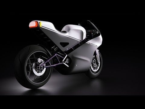
The body of work shown in the video was done of a three day weekend with a total time investment of appoxiamately 27 hours. The vision was to for concepting an an super crazy electric racing bike with a retro flair.
Step 1 – Photo Bash Bike Underlay Image
2D Underlay Reference -Motorcycle photos bashed using Adobe PS and AI
Step 2 – Model Mode | Construct Using Simple Extrudes & Revolves
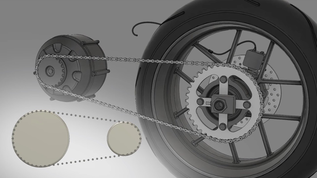
Multi-body component geometry construction using extrudes and revolves. The COMBINE tool was used to make components.
Design chain first using pattern feature. Afterward, match sprocket divisions to the chain.
Step 3 – T-Spline Mode | SubD Modeling for Body Panels
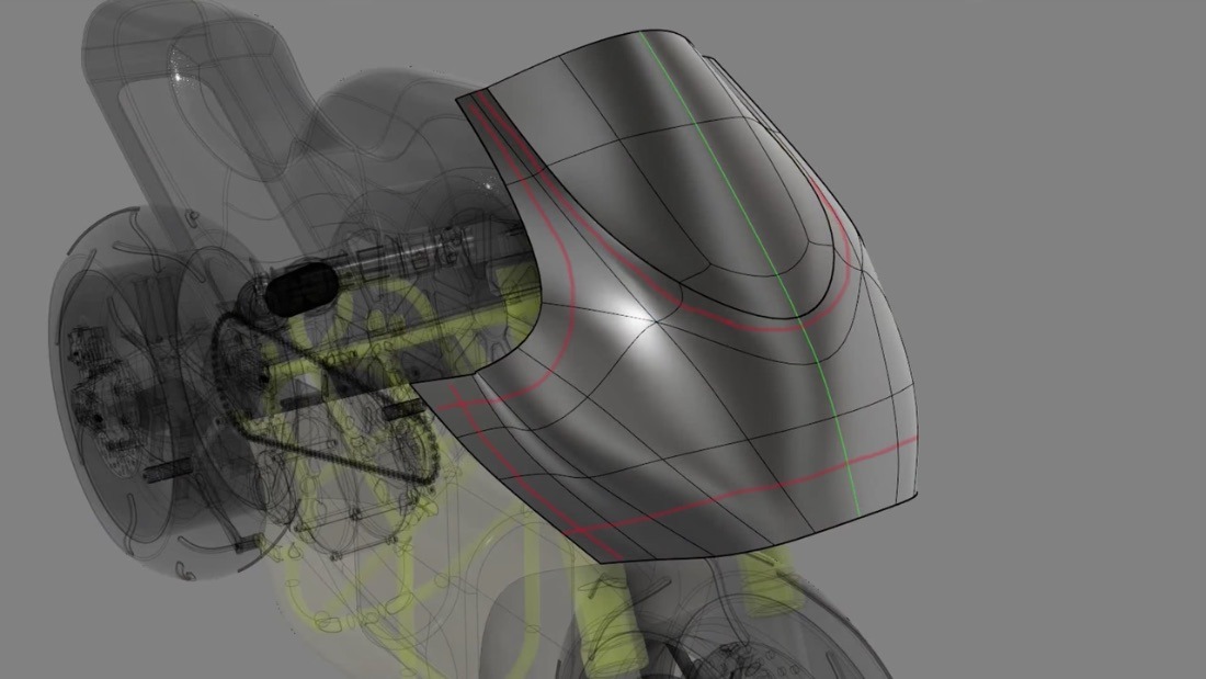
T-Spline SubD sculpted geometry construction. Four edge loops define perimeter with the middle filled in.
T-Spline SubD sculpted geometry construction. Patch division requires star points and becomes harder to control flow.
T-Spline SubD sculpted geometry construction. T-Spline body later converted to B-Rep.
T-Spline SubD sculpted geometry construction. T-Spline body later converted to B-Rep.
Step 4 – Patch Mode | Component B-Rep Surface Construction
Patch Mode B-Rep surface geometry construction. Other quilts are used to trim or by stitching to complete cover.
Step 5 – Render Preparation | Sizing & Edge Rounds Used to Enhance Hights
Reduce tubing size on cross tubes to help Edge rounds flow and improve highlight distribution in rendering.
Edge rounds added to all component whether needed or not to improve highlight distribution in rendering.
Step 6 – Model Rendering | Design Component Alternatives Comparison
Trailing arm modification made to improve design aesthetics and enable all parts t fit.
Final design overlayed on original reference concept. Changes were made to areas where the 2D profile did not make sense in the 3D space.
Vince has worked as Studio Engineer for consumer and medical product brands such as Whirlpool, Newell and ResMed Ltd. Australia. He's garnered 39+ patents and has designed everything from totes to toasters, and fiddles to furniture. He enjoys all things 3D and has carved out a niche as a Class-A Surfacing Guru. Active in both industry and academia, Vince serves as a Creative and Technical Skill Development Coach providing hands-on training and workshops pertaining to CAID/CAD. Vince relishes opportunities to keep learning and sharing what he's learned!