Parallel utilities can produce a stable locator response over the wrong line. The receiver may show a clear peak, a believable depth, and a consistent compass direction. None of those readings proves that the signal belongs only to the target utility.
Modern radiodetection locators provide several ways to check the signal field, including Peak, Null, current, depth, and Current Direction. These functions help the operator identify distortion. They cannot remove distortion from the ground.
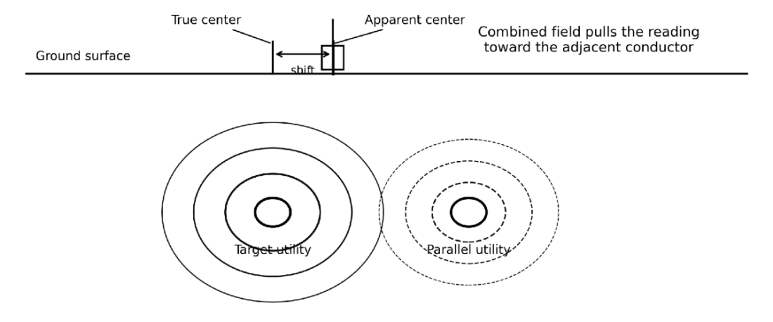
The main problem is simple: the receiver detects an electromagnetic field, not the physical cable or pipe. When two parallel conductors carry the same locating frequency, the receiver measures their combined field. That field can shift the apparent centerline, corrupt the depth estimate, or pull the operator onto another utility.
This article explains how that happens and how to recognize it before marking or drilling.
What We Reviewed
This research uses current and recent operating documents for:
- Radiodetection RD8200SG;
- Vivax-Metrotech vLoc3-5000;
- Subsite UtiliGuard 2;
- OSHA excavation and utility-location requirements.
The manufacturer manuals describe operating functions and known limitations. They do not provide a controlled comparison of all three systems under identical field conditions.
That distinction matters. Manufacturer warnings explain what can happen. They do not establish a universal error rate for every jobsite.
Why Parallel Utilities Distort the Signal Field
A transmitter places alternating current on a conductive cable, pipe, or tracer wire. That current creates an electromagnetic field around the conductor.
The receiver measures the field and calculates its apparent center. Under clean conditions, the field remains roughly symmetrical around one conductor. The strongest Peak response appears over the utility, and the calculated depth follows the expected field gradient.
Parallel utilities change that geometry.
A nearby conductor can receive part of the signal through three main paths:
1. electromagnetic coupling between nearby conductors;
2. a shared electrical bond or grounding system;
3. return current flowing back toward the transmitter.
The receiver then measures more than one field.
Electromagnetic Coupling
Electromagnetic coupling transfers part of the active signal from the target utility to another nearby conductor. The two utilities do not need a direct metallic connection.
Coupling becomes more likely when:
- the utilities run parallel for a long distance;
- the distance between them is small;
- the selected frequency is high;
- the transmitter uses broadcast induction;
- the adjacent conductor provides an effective current path.
Subsite states that lower frequencies travel farther, while higher frequencies couple onto utilities more easily. Radiodetection also warns that higher frequencies transfer more readily onto unwanted lines.
A high frequency may solve one problem and create another. It can place more current on a difficult target, but it can also spread the signal across the corridor.
Shared Bonds
Two utilities can carry the same locating signal because they share a bond.
Common bond points include:
- building grounds;
- cabinets;
- pedestals;
- cable shields;
- grounding grids;
- transformer installations;
- cathodic protection systems;
- utility structures with several metallic connections.
The signal can leave the intended conductor at the bond and continue along another cable or pipe. Both routes may then produce convincing receiver responses.
Vivax-Metrotech warns that a non-target line bonded to the target can appear synchronized with the target when the operator uses Signal Direction.
Direction data helps. It does not override the electrical circuit.
Ground-Return Paths
Current must return to the transmitter.
With a standard direct connection, the transmitter sends current through the target and receives it through the soil and ground stake. A nearby cable or pipe can become part of that return route.
Ground-stake placement therefore affects both signal strength and selectivity.
A ground stake placed across another utility can pull current onto that utility. A stake connected to a bonded structure can distribute the signal across several conductors. The operator may improve transmitter output while reducing confidence in the target identity.
The best electrical ground is not always the cleanest locating ground.


What the Receiver May Show
Parallel-line distortion does not create one standard display pattern. The result depends on relative depth, spacing, current, route geometry, frequency, conductor size, and bonding.
The following symptoms deserve closer checks.
| Receiver symptom | Likely mechanism | Main risk |
|---|---|---|
| A shallow parallel line shows the strongest response | The receiver is closer to the non-target field | The operator marks the wrong utility |
| One broad peak appears between two routes | Two fields overlap | The marked centerline may fall between both utilities |
| Peak and Null appear at different positions | The field is asymmetrical | The apparent line position has shifted |
| Depth changes sharply on a straight route | Current transfers or field geometry changes | The depth estimate no longer represents one conductor |
| Current jumps onto another route | A bond, tee, fault, or return path changes current distribution | The operator follows the wrong branch |
| Direction remains positive on two utilities | The conductors share a bond | Direction data cannot separate them |
| The signal weakens beside a structure | Metal shields or distorts the field | The operator may assume the utility ends |
One symptom does not identify one cause. The operator must compare several readings.
The Strongest Response May Belong to the Wrong Utility
Signal strength depends on both current and distance.
A shallow conductor carrying moderate coupled current can produce a stronger response than a deeper target carrying more current. The receiver may therefore place the largest bar graph over the wrong line.
Radiodetection recommends using current measurements to help identify a connected target where several lines carry the same signal. Current compensates for depth better than raw response strength.
Current still needs context.
A common bond can divide current across several utilities. Field distortion can also affect the receiver’s current estimate. The operator should compare current along the route instead of relying on one reading.
A stable trend provides more evidence than one high value.
Peak and Null Disagreement Reveals Distortion
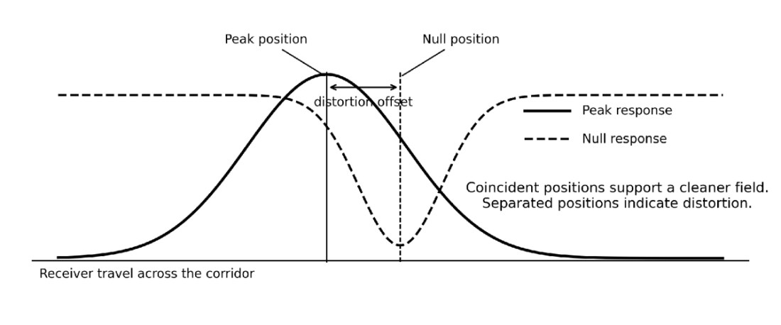
Peak and Null use different antenna responses.
Peak finds the maximum field response. Null finds a minimum response over the apparent field center. In a clean and symmetrical field, both positions should closely correspond.
Radiodetection states that a Peak maximum which does not match the Null point indicates a distorted field. The company also warns that Null is more vulnerable to interference and should not serve as the only locating mode in congested areas.
Use the two responses for different jobs:
- use Peak for the primary pinpoint;
- use Null to test the field;
- compare both positions before recording depth;
- repeat the comparison farther along the route.
Do not average the two marks and call the midpoint correct.
Radiodetection’s RD8200SG manual states that the true line should normally remain closer to the Peak position when Peak and Null disagree. That guidance applies to the field condition and equipment described in the manual.


Parallel Lines Can Produce Large Depth Errors
A locator calculates depth from the strength and shape of the detected field. That calculation assumes a suitable field from one target.
A second conductor changes the field gradient. The displayed number can move higher or lower even when the physical utility stays at a constant depth.
Radiodetection gives a specific warning for the RD8200SG. Its manual states that a significant signal on an adjacent line within 1–2 m (3–6 ft) can introduce a depth error of ±50%. The manual describes this as a common depth-error source.
This figure needs a clear qualification.
It is a manufacturer warning, not an industry-wide average. The manual does not provide the conductor sizes, soil properties, frequencies, current ratios, or test sample behind the figure.
The practical conclusion remains valid: an adjacent signal can make a believable depth reading seriously wrong.
Radiodetection also states that locator depth serves as a guide. The operator must not use it to define mechanical digging depth.
Use a Lift Test Before Trusting Depth
A lift test checks whether the displayed depth changes as expected.
Follow this process:
1. Pinpoint the utility in the recommended Peak mode.
2. Hold the receiver vertical and correctly oriented.
3. Record the displayed depth.
4. Raise the receiver by a measured distance.
5. Repeat the depth reading.
6. Compare the difference.
The displayed depth should increase by approximately the same distance that you raised the receiver.
The RD8200SG manual uses a 2 in. (50 mm) lift as a quick check. Other manufacturers may specify another distance or procedure. Follow the manual for the exact receiver.
A failed lift test does not identify the cause. It tells you that the depth reading needs more investigation.
How Signal Application Changes the Risk
The signal application method controls how selectively the transmitter energizes the target.

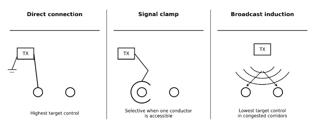

Direct Connection
Direct connection usually gives the best control because the operator connects the transmitter to a known conductor.
It also supports lower frequencies more effectively than induction. Lower frequencies usually reduce unwanted coupling and travel farther along a suitable conductor.
Direct connection still has limits:
- common bonds can split the current;
- a poor ground can reduce the usable signal;
- ground placement can create a misleading return path;
- the connection point may sit inside a bonded network;
- energized systems can present a lethal electrical hazard.
Only qualified personnel should connect locating equipment to energized or potentially energized infrastructure. The operator must use the approved leads and procedures for the specific transmitter.
Signal Clamp
A signal clamp applies current without direct metallic contact.
The clamp can improve selectivity when the operator can place it around one accessible cable or pipe. The clamp must close completely, fit the conductor, and support the selected transmitter frequency.
The circuit still needs a return path.
A clamp around a cable group, bonded sheath, or multi-conductor installation may place signal beyond the intended route. A clamp reduces direct broadcast. It does not guarantee isolation.
Broadcast Induction
Broadcast induction offers the least control around parallel utilities.
The transmitter creates a field that induces current onto conductors below and around it. In a congested corridor, several utilities may receive the same frequency.
Vivax-Metrotech advises against induction when identifying cables because the signal can appear on every cable near the transmitter.
Induction still has a valid role. It helps with area sweeps and unknown-line searches where the operator cannot access a connection point.
Use it as a search method, not automatic proof of identity.
| Application method | Target control | Parallel-line risk | Best use |
|---|---|---|---|
| Direct connection | Highest | Lowest when the circuit is properly controlled | Tracing a known accessible conductor |
| Signal clamp | Medium to high | Depends on bonds and cable configuration | Applying signal without metallic contact |
| Broadcast induction | Low | Highest in congested corridors | Searching for unknown conductive utilities |
Start With the Lowest Usable Frequency
Frequency selection requires a trade-off.
A low frequency usually stays on the target better and travels farther. A high frequency couples more easily but can energize short, small, poorly grounded, or high-impedance conductors more effectively.
Use this sequence:
1. start with a low active frequency;
2. confirm that the target carries usable current;
3. trace the route and check current stability;
4. increase frequency only when the lower setting cannot support the locate;
5. repeat every distortion check after changing frequency.
Do not assume that a stronger response means a better locate.
The better setting produces a traceable target with less response on adjacent utilities.
Direction Identification Helps, but It Has Limits
Several current locator systems provide a direction or phase function.
Examples include:
- Current Direction on the Radiodetection RD8200SG;
- Signal Direction and Signal Select on configured Vivax-Metrotech vLoc3-5000 systems;
- Direction Enable on the Subsite UtiliGuard 2.
These functions help distinguish signal flowing away from the transmitter from return current flowing toward it.
They use model-specific transmitters, frequencies, accessories, options, and procedures. The functions are not interchangeable.
A direction feature can fail to separate commonly bonded conductors. Vivax-Metrotech states that a bonded non-target utility may also appear “in sync” with the target.
Use direction as one identity check. Combine it with:
- Peak and Null agreement;
- current comparison;
- route continuity;
- access-point evidence;
- depth trends;
- physical exposure.
A Practical Workflow Near Parallel Utilities
The following sequence reduces the chance of marking the wrong line.
1. Review the Site Before Applying a Signal
Check the 811 ticket, utility-owner responses, drawings, visible structures, previous markings, valves, pedestals, meters, cabinets, and manholes.
Map every route that could run through the work area.
2. Sweep the Full Corridor
Run a systematic passive sweep before tracing one target.
Use the available passive modes that fit the site. Passive signals can reveal unknown conductive utilities, but they usually provide weak identity evidence.
Mark every consistent response for further checking.
3. Find the Cleanest Access Point
Choose a direct connection or clamp point outside the most congested section where possible.
Avoid applying the signal at a common building ground or cabinet until you understand the bonds.
Trace toward the congested area. Do not begin inside it without a reason.
4. Control the Return Path
Place the ground stake away from the target and other suspected utilities.
Keep the ground lead from crossing another buried route where practical. Do not use a convenient metallic structure as the ground unless you know how it connects to the surrounding system.
5. Start Low
Select the lowest frequency that produces stable and usable target current.
Check adjacent routes before increasing transmitter output or frequency.
6. Trace in Peak
Follow the target through several points.
Record:
- Peak position;
- current;
- depth;
- signal strength;
- frequency;
- direction status;
- changes in route geometry.
Watch trends rather than isolated numbers.
7. Compare Peak and Null
Check both positions at straight sections.
Repeat the test near any point where current, direction, or depth changes. Treat increasing separation as evidence of stronger distortion.
8. Run the Lift Test
Check critical depth readings before using them for planning.
Reject the reading when the change does not match the receiver lift.
9. Reapply the Signal
When the result remains ambiguous:
- move the connection point;
- move the ground stake;
- lower the frequency;
- use an approved clamp;
- trace from the opposite end;
- use a double-ended connection where authorized;
- have the facility owner isolate a bond;
- trace each parallel route separately.
10. Expose Critical Crossings
Stop relying on electromagnetic inference when you cannot establish one clear target.
OSHA requires employers to determine the estimated location of underground installations before excavation. As excavation approaches the installation, the employer must determine the exact location through safe and acceptable means.
A locator mark supports that process. It does not finish it.
Readings the Crew Should Reject
The crew should not accept a critical mark or depth when:
- Peak and Null remain separated;
- the lift test fails;
- two routes show similar current;
- direction identification supports more than one utility;
- the depth changes without a route or grade explanation;
- the signal transfers at a bond or junction;
- passive mode provides the only usable response;
- records, surface evidence, and locator results conflict;
- induction produces several similar traces;
- the receiver stands too close to the induction transmitter;
- the target crosses another high-consequence utility.
These conditions do not always mean that the locator has failed.
They mean that the field cannot support the required confidence.
Key Findings
Parallel utilities distort locator readings because the receiver measures a combined electromagnetic field.
The wrong utility may show the strongest response. A shallow coupled line can overpower a deeper target on the display.
Peak and Null disagreement provides a practical distortion warning. Peak should guide the primary pinpoint, while Null should test field quality.
Depth can remain believable while being seriously wrong. Radiodetection warns that strong signal on a nearby parallel line can produce errors as large as ±50% under the conditions described in its RD8200SG manual.
Higher frequencies increase coupling risk. Start with the lowest frequency that produces a usable target signal.
Direct connection usually gives the best selectivity. Broadcast induction gives the least control in a congested corridor.
Current and direction functions improve identification. Common bonds can still mislead both.
The crew must expose a critical utility when the readings remain ambiguous. The locator narrows the search area. Physical verification establishes the crossing.