")
Presented by
![]()
The O’Jays. Remember those guys? Probably not, but I guarantee you’ve heard their most popular song, For the Love of Money. Two chords and a repetitive five-word phrase later, and you’ve got a song stuck in your head for longer than you want. Those could easily be five reasons integrated CAM matters to engineers. But alas, we know engineers are not that superficial. So, in our final foray into Fusion 360 features, we’re going to look at something you shouldn’t overlook–its integrated CAM functionality.
But rather than talk waaaaay out of my proficiency about CAM features like toolpath setup, tool libraries, roughing & finishing, and all things CAM as though I’m Machine Shop Billy flicking cutting oil in your eye, I’ll take a slightly different path. I’d like to talk about the steps to understanding CAM in Fusion 360, but in the context of what it does to help (crank the reverb) ENGINEERING TEAMS.
Before You Even Start Modeling
When first working in a manufacturing environment, I asked myself, what manufacturing processes do I need to know? And, why do I need to know them? Fortunately, Shop Manager Mike heard me and broke it down for me in simple terms and foul language with three things to think about before slapping model geometry together.
Materials – Mike: “You’ve got to know what’s available and what’s commonly used, you stupid #$*%ing engineer. Think of stock size, @$$#0&%, and ways to reduce waste!”
Tools – Mike: “If I have to change that tool more than twice, I’ll kill you *!$#&%. Even a basic part is going to have, at the very least, two setups. I smoke with this hand and this one only has three fingers!”
Rework – Mike: “If I have to redo any of your $#!%, I will beat you with that #%&(@! useless 20-sheet drawing. Then you’ll know how much someone can bleed on a piece of $%&*@in’ paper! $H%$*#!”
I’m so thankful for Mike and the time he took to help me understand the basics of the manufacturing process. True enough, these are things many designers and engineers are not privy to until they’re in the thick of it. Right up front, get to know the process. What is and isn’t possible. What processes make the transition from engineering to manufacturing go more smoothly. This way, before something is handed off to the shop, the likelihood that it can actually be manufactured will be more than just a guess.
This, of course, is where integrated CAM comes in. I’m looking at this, not from becoming an overnight CNC success, but to better understand HOW toolpaths are created and how it can be an aide in the product dev process. At the very least it provides insight. At most, it saves time, material and rework, which helps save… cue the O’Jays. So let’s take a step-by-step look at features I wish I had along the way, features I think will become increasingly important to engineers and designers, while keeping Mike’s gentle words in the back of our head.
Step 1. Creating the Setup
Suddenly you have a final part. Hours spent modeling. It’s perfect. You considered size and stock material availability, even the position it was modeled it in. But let’s not get too far ahead. The first feature we can use in setting up a toolpath is determining a Work Coordinate System (WCS). Even if you didn’t model it in the correct position or know for how the part is going to be machined, The Fusion 360 CAM setup can help set the WCS with the quick selection of an edge to properly orienting the model for the machine.

Step 2. Roughing
A quick definition here – Roughing a part is removing as much material as possible in the shortest amount of time as possible. Fusion 360 does this with the Adaptive Clearing feature. We touched on this in our first article, but if you don’t know what Adaptive Clearing is like from a machinist point of view, read this article. To simplify it for myself, I look at it like this (tell me if I’m wrong): Adaptive Clearing utilizes an adaptive algorithm that applies a constant tool load to the clearing path so any overloading on the machine tool is prevented, ensuring uniform wear across the tool, thus increasing the life of the tool. This is where I would make the recommendation to involve the machinist in what you are doing. Get his or her feedback (and confidence) about how you’re approaching the design, not to do what they’re doing, but to make sure it can be done and in the long-run, reduce their work or re-work.

Step 3. Finishing
To grossly oversimplify finishing, this is where you remove the material that was left behind after roughing. There are an infinite number of possibilities here. An infinite number of machine tools, tool types, and combinations thereof. What Fusion 360 brings to the table here is a repeatable, consistent method to apply an unlimited number of machining solutions via a consistent interface no matter the process.

Step 4. Toolpathing
Every toolpath has the same basic setup. In Fusion 360, I’ve got to say, it’s both intuitive and also overwhelming. Let’s look at each tab.

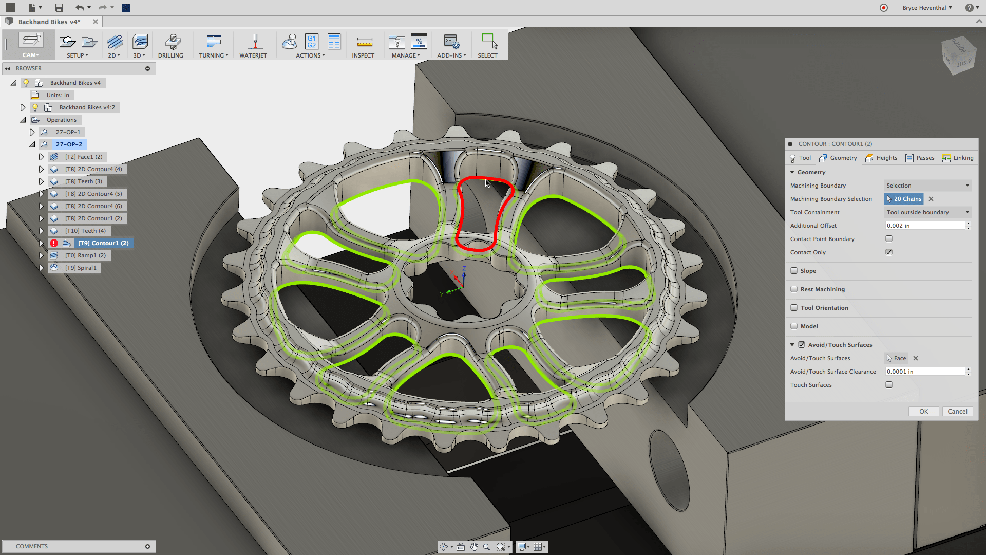

Passes Tab – In general, this is where you would set the step over, the step down, the amount of stock to leave, etc.–It’s where you tell the tool how to remove material.
Linking Tab – Here is where you can save time by changing how the tool moves between cutting operations. You have Full, Minimum, and Shortest Path retraction options. Basically, you control the travel of the cutting head while it’s not cutting anything.
These 5 tabs are repeated for EVERY single 2D, 3D, Turning, and Waterjet cutting operation. So, as I stated earlier, while you have an infinite number of outcomes, the process to define them is finite and repeatable. This makes learning, applying, and troubleshooting easier for everyone.

Step 5. Simulating
This is where you find out if you’re going to completely ruin your part, break your tool, crash your machine, or hopefully, make the part without error. The default options work well to see a simulated cutting operation. You can turn on or off the toolpaths to get yourself a better view of the action, simulating everything but the metal shavings and oil flying off the piece.

Step 6. Post Processing
Fusion 360 comes with 100+ generic post configurations that are setup to create the G-code that can be loaded into the machine tool. Beyond that you can visit cam.autodesk.com/posts to find hundreds more (free, btw).
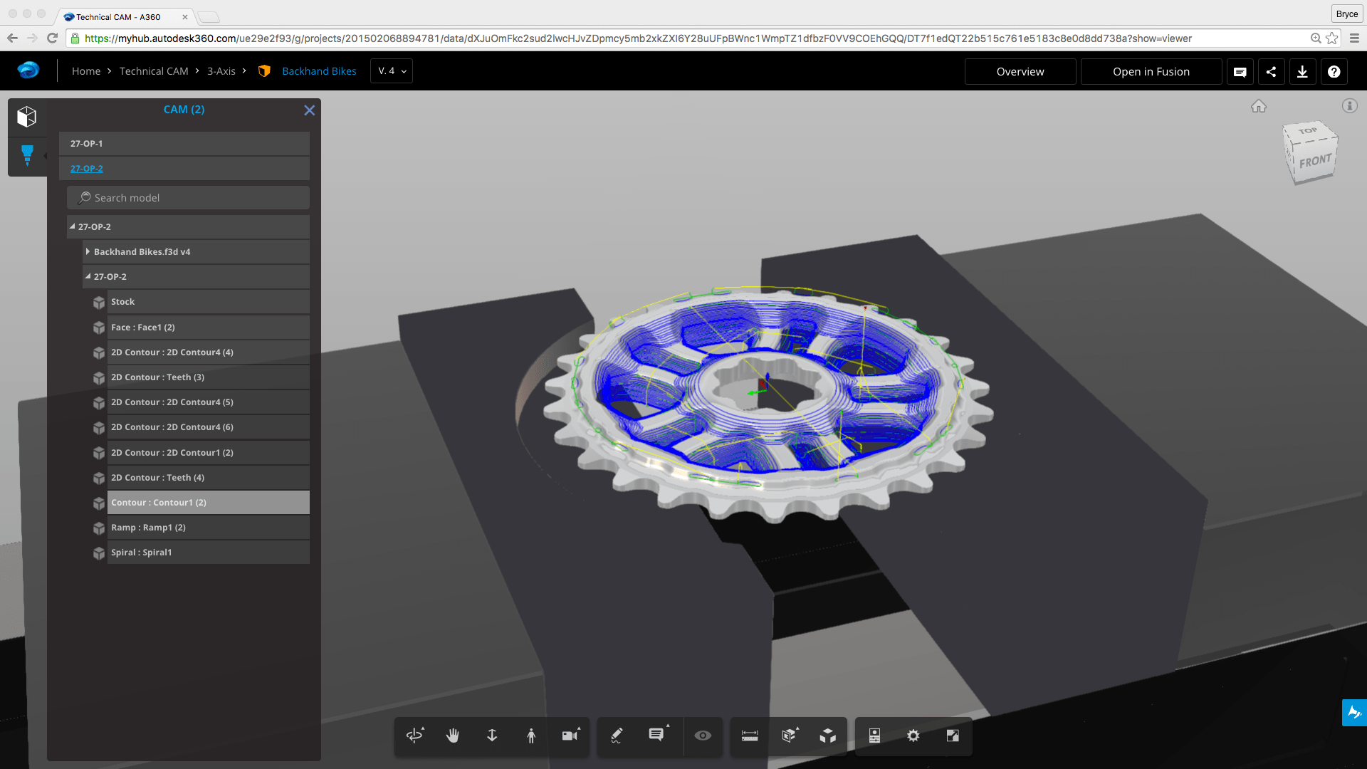
Why should all this matter to engineering teams? Ch ch ch changes. All of these steps have been happening in the same interface we use to create the model. Even the smallest change and the CAM automatically updates the toolpath. In a engineering-manufacturing environment this in invaluable. Along with this, and particularly useful if you work with an offsite machine shop, toolpaths created in Fusion 360 can be viewed in a web browser before sending the job off to the machine. In either case, all of this allows the machinist onsite or offsite to see what the machine is going to do before they hit the green button.
So, what is Fusion 360? We started off exploring Fusion 360 to see if it passes the claim that it’s more than just CAD in the Cloud. Honestly, when I’m using it, I’m not thinking about that aspect, but at the same time, there are those ‘cloud’ features that complement the process–the collaboration, the viewing, and offloading operations. The sculpting, part and assembly modeling are so different from what I’ve experienced before and when you combine that with the collaboration, and then the simulation and then the CAM capability, it’s certainly more than just CAD. And with all of that, yeah, I suppose a bit more than just CAD in the Cloud.
For $300/year, there’s even a compelling argument that Fusion 360 delivers a whole other level of value outside of typical CAD tools, through a set of integrated tools that uniquely become an integrated process that captures the whole of product development. A Product Innovation Platform? I suppose you have to call it something (Product Innovation Arsenal would have been so much better), but I think that actually sells it a little short. You provide the innovation. Fusion 360 provides the comprehensive set of tools. It’s you being able to capture everything needed to make an idea happen. That’s powerful. And when you have that product in your hand, that’s more than a platform.
This is the last of this series, and I’m even more curious now to hear from people and companies who are using Fusion 360 and how they are using it. If you haven’t yet, try Fusion 360 here and then tell us your story. We would love to hear it.